Safety Glasses
 Nitrile Gloves
 CV Axle Shaft
 Wheel Chocks
 Floor Jack
 Jack Stands
 Ratchet and Socket Set
 Torque Wrench
 Needle-Nose Pliers
 Flathead Screwdriver
 Hammer
 Ball Joint Press
 Axle Nut Socket Set
 Breaker Bar
 Drain Pan
 Shop Towels
 Anti Seize
 Steering Knuckle Bolts
 Axle Nut Locks
 Cotter Pins
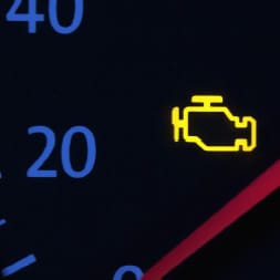
Constant velocity shafts, also called CV shafts or CV axles, transfer power from the differential or transaxle to the hub of the vehicle to power the wheels. CV joints used on both ends of the shaft allow it to articulate freely when turning or driving over uneven terrain, and are lubricated with grease to prevent premature failure. A failing CV shaft may make ticking or clunking noises, especially when turning, and complete failure can prevent your vehicle from being driven, so regularly inspecting your CV shaft is a good idea to keep from an untimely breakdown.

Your vehicle’s CV axle has two joints—an inboard joint at the transaxle or differential, and an outboard joint at the wheel. These CV joints are protected by rubber boots which also keep the joints greased and free from dirt or debris. If one of the rubber boots cracks or splits, the grease protecting the joint can leak out, dirt and debris can make their way into the boot, and this can cause damage to the joint.
- If you hear noise and feel vibration when you accelerate in a straight line, your inboard joint may be damaged.
- If there is clicking, knocking or binding when you turn sharp corners, your outboard joint may be damaged.
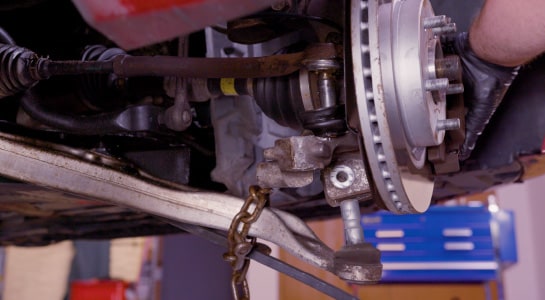
If either of your CV joints are damaged, you’ll need to lift and support the vehicle and remove the wheel or wheels where you’ve noticed the symptoms.

Look at the boots to see if there are any signs of damage or leakage. If there is damage, at the very least, a damaged boot needs to be replaced. You can also take hold of the axle shaft and try to shake or move it. If there’s excessive play, chances are the joint is worn out or failing.

Step 1: Prepare Your Vehicle
If you haven’t done it already, park on a level surface and chock your rear wheels. Loosen the wheel lugs and then lift and support your vehicle’s front end.
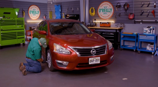
Remove the lugs and remove the wheel or wheels where you need to work.

Step 2: Remove Your Rotor Cotter Pin
Use needle-nose pliers to remove the cotter pin from the axle nut.

Step 3: Remove Your Axle Nut Retainer
Remove the nut retainer.

Step 4: Remove Your Axle Nut
Loosen and remove the axle nut using an axle nut socket and breaker bar. To keep it from spinning, have a friend step on the brake pedal if needed.

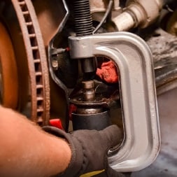
Step 5: Separate Your Axle Shaft from Your Hub
Use a front wheel drive hub press to separate the axle shaft from the hub bearing. Once the hub puller is attached to the hub, make sure it’s tight.
Use a ¾” or 19mm wrench or ratchet and socket to turn the shaft clockwise and apply pressure to the axle shaft until it’s pressed all the way through the hub.

Step 6: Remove Your Mounting Nut
Remove the tie rod end from the steering knuckle, starting with the cotter pin then use your ratchet and socket to loosen the mounting nut.

Leave the mounting nut at the bottom of the bolt to protect the bolt and use a hammer to tap the bolt up through the steering knuckle. Once it’s been loosened, remove the nut.
|
Do It Right: Pull the tie rod end up and out of the knuckle and move it to the side. Be careful not to damage the tie rod end! |

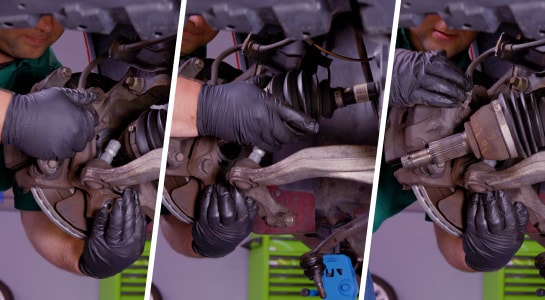
Step 7: Disconnect Your Ball Joint
Separate the ball joint from the steering knuckle, starting by removing the nut and bolt at the bottom of the knuckle.

Once the nut is removed and the bolt is broken loose, use your hammer and punch to tap the bolt out.
Use a ball joint separator, a pry bar, or another separator tool to disengage the ball joint from the steering knuckle. Make sure not to damage the ball joint or control arm. Once they’re separated, carefully move the knuckle out of the way.
Step 8: Separate Your Axle from the Hub
You should be able to pull the axle through and separate it from the hub bearing.
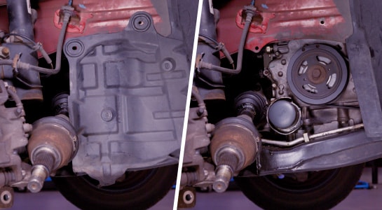
The other side of the axle is at your transaxle or differential. In our case, we’ll need to remove a splash guard to access it.

Step 9: Remove Your CV Bolts and Brackets
Remove the bolts and bracket holding the CV axle in place. It should slide out of the transaxle and bracket easily. If the bearing is seized to the bracket, you may have to take additional steps.
In our case, we were unable to remove the CV axle bearing from the bracket, which was required in order to remove them as an assembly. This involved removing the 13mm axle retainer bolts as well as the three 18mm bolts for the bracket.

Step 10: Remove Your Oil Cooler Bolts
Remove the five 10mm bolts from the oil cooler on the engine to provide clearance for the CV axle and bracket to be removed.
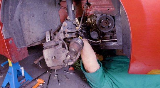
Step 11: Separate Your CV Axle from Your Transaxle
Put a drain pan under the joint and use a pry bar to carefully separate the CV axle from the transaxle and remove the assembly from the vehicle.

Remove the seized bracket from the CV axle bearing, being careful to work it off slowly with a hammer and punch all around the diameter of the bracket to prevent further binding. Use a shop towel or rag to wipe down the seal at the transaxle or differential.

Step 12: Install Your New CV Shaft
Inspect the seal to make sure there are no signs of damage. If the seal looks good, install your new CV shaft, starting at the transmission.
|
Do It Right: If you had to remove the CV axle bearing bracket and oil cooler, you’ll also need to reinstall them before proceeding. |

Step 13: Reinstall Your Bracket Bolts and Oil Cooler Seals
Reinstall the three 18mm bolts through the CV axle bracket, and torque these to 35 foot-pounds. Replace the seals behind your oil cooler, and reinstall the five 10mm bolts, torquing them to 80 inch-pounds.

Step 14: Reinstall the Shaft
Insert the shaft, turning it slightly back and forth to make sure you align the splines before you carefully push in.
Once you’re sure the shaft and internals are in proper alignment, use a rubber mallet to gently tap the axle in so that it’s fully seated.

Step 15: Reinstall Your Axle Retainer
Reinstall your CV axle retainer using the 13mm bolts you removed earlier. Torque these bolts to 18 foot-pounds.

Step 16: Lubricate Your Axle Shaft
Apply anti-seize lubricant to the splined portion of the outer end of the axle shaft. This will help if the CV axle or other parts need to be replaced in the future.

Move the steering knuckle out slightly so that you can maneuver the shaft into the hub bearing.

Step 17: Reinstall Your Ball Joint
Reinstall the ball joint into the steering knuckle, making sure the axle shaft is seated in the wheel bearing. Check to make sure the ball joint is completely seated in the knuckle.

Step 18: Reinstall Your Steering Knuckle Bolt
Reinstall the steering knuckle bolt. Once installed, thread the nut, and tighten to manufacturer specification.

Reinstall the outer tie rod end through the steering knuckle. Once seated, reinstall the washer and nut and tighten the nut to manufacturer specification.

Step 19: Install Your Tie Rod Cotter
Install a new cotter pin at the end of the bolt. Reattach your splash guard.

Step 20: Reinstall Your Axle Nut
Thread your axle nut into place until it’s firmly seated then tighten it to manufacturer specification. To keep it from spinning, have a friend step on the brake pedal if needed.

Reinstall the nut retainer and install a new cotter pin.

Step 21: Lower Your Vehicle
Reinstall and tighten your wheel’s lug nuts and lower the vehicle.

Remove the wheel chocks and tighten the lug nuts in a star pattern to manufacturer specification.
|
Do It Right: You may need an alignment once the job is done. Keep this in mind before driving anywhere, and plan accordingly. Check out our helpful article about car handling basics. |